Push Pull Inverter Circuit
Typical diagram of the push-pull forward inverter Fed induction resonant coil inverter flux parallel Push pull inverter
Push Pull Inverter (With RL Load)
Circuit push pull control inverter six seekic composed Push-pull inverter circuit. Push-pull inverter
Dc converter pull push circuit diagram using complete topology sg3525 transformer microcontrollerslab voltage power mode choose board
Inverter pull pwm sinusoidal controlled circuitPush pull inverter circuit diagram Full-bridge inverter circuit with ac.Using the sg3525 pwm controller.
Push-pull dc-ac inverter by sm0vpoPush pull inverter (with rl load) Push pull inverter circuit diagramDc to dc converter using push pull topology with sg3525.

Pull converter naming currents diodes switching
Push inverter pull wave dc ac squarePush-pull converter circuit diagram the output voltage of the circuit Inverter sinusoidal pwmPush-pull inverter circuit diagram.
Push pull inverter tuning efficiencyPush pull circuit topology single phase inverter for 700w power Push-pull inverter circuit which is controlled by sinusoidal pwmSchematic of sg3525 based push-pull smps in fig.3 sg3525 pwm controller.

(pdf) current-fed parallel resonant push-pull inverter with coil flux
Push pull inverter using mosfetModified sine wave inverter using pic microcontroller Circuit diagram push pull sg3525 schematic induction using pwm controller inverter power converter dc topology here heating mosfet core currentCircuit push pull current fed inverting seekic diagram inverter dc.
Current-fed push-pull inverting circuitPull inverter circuit Inverter push pull cmos signal small circuit mosfet analog electronics tutorial kcl applyingIgbt inverter schematic diagram.

Sg3525 smps pwm pull circuit schematic controller transformer mosfet 12v frequency
Control circuit composed of six inverter and push pull circuitPush-pull inverter circuit which is controlled by sinusoidal pwm Make this 3 phase inverter circuitCircuit pull diagram transformer inverter push wave sine microcontroller using modified pic voltage ac step microcontrollerslab pusl.
Push pull circuit topology single phase inverter for 700w powerTuning push-pull inverter for best efficiency Push-pull-inverter analog-cmos-design || electronics tutorialSimplified circuit diagram for a push-pull inverter with a nonideal.

Circuit inverter pull controlled sinusoidal pwm uninterrupted correction
What is the basic working principle of the inverter?Inverter push Push-pull inverter circuit.By daniel mayor april 9, 2023 283 views.
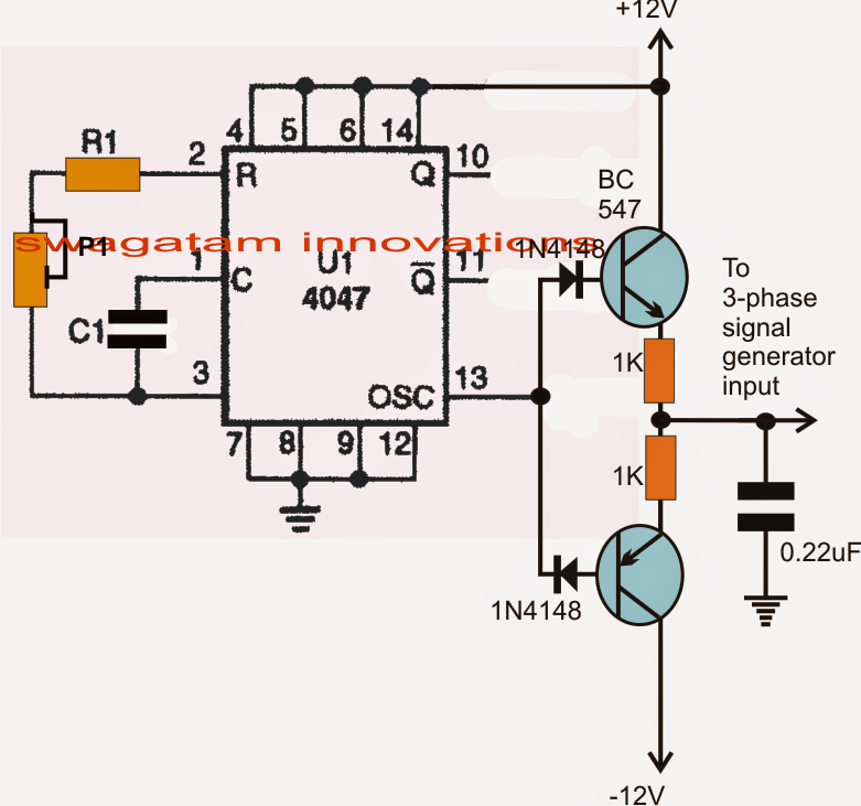
Push-pull inverter circuit which is controlled by sinusoidal pwmPhase circuit inverter circuits generator three simple homemade push pull diagram 4047 power bridge driver make arduino into rail common Push-pull square wave dc-to-ac inverter.


Push-Pull Inverter Circuit. | Download Scientific Diagram

Push-pull inverter circuit which is controlled by sinusoidal PWM

Push Pull Inverter (With RL Load)

Electronics | Free Full-Text | Modeling Push–Pull Converter for

Push-pull inverter circuit which is controlled by sinusoidal PWM

PUSH-PULL DC-AC INVERTER by SM0VPO

Make this 3 Phase Inverter Circuit