Push Pull Transformer Circuit Diagram
Transformer push–pull output push–pull converter alternating current Push pull output transformer design Transformer converter calculation core
Push pull class b amplifier wiki
Uses of push pull amplifier Push pull converter dc high frequency transformer voltage isolated driver analog figure fixed count input low parts Push pull output transformer design
Dc converter pull push circuit diagram using complete topology sg3525 transformer microcontrollerslab voltage power mode choose board
Class b push pull amplifier circuit diagramAmplifier circuit class ab pull push diagram transistor amplifiers circuitdigest audio circuits crossover choose board saved Iwistao blogger : what is a pull-push output transformer?Schematic diagram of the 4-way transformer-based push-pull power.
Push–pull with transformer.Push pull output transformer design Circuit pull diagram transformer inverter push wave sine microcontroller using modified pic power voltage ac step pusl microcontrollerslabThe secondary voltage of the push-pull transformer..

Push pull converter transformer design
The equivalent circuit of the push-pull transformer.Pull push transformer high switching voltage circuit cet technology smps isolated open output inductor ignore capacitor concentrate going re only Dc to dc converter using push pull topology with sg3525Push pull transformer circuit diagram.
Push-pull amplifierMosfet push pull amplifier circuit Using push-pull transformers to isolate power in 12v applicationsTransformer push seekic.

The push-pull circuit diagram without output transformer
Schematic of sg3525 based push-pull smps in fig.3 sg3525 pwm controllerDc circuit converter push pull diagram sg3525 using topology microcontrollerslab Class b push pull amplifier experiment theorySg3525 smps pwm pull circuit schematic controller transformer mosfet 12v frequency.
Work, voltage, and powerClass b push pull amplifier circuit diagram Push pull class b amplifier wikiPush pull mosfet amplifier diagram.

Circuit push mosfet pull amplifier amplifiers diagram
Push pull amplifier circuit diagramDc to dc converter using push pull topology Push pull switching transformer designPush pull output transformer design.
Push pull output transformer designPush-pull center tap converter transformer design (pdf) push-pull circuits and wideband transformersLesson work voltage solution.

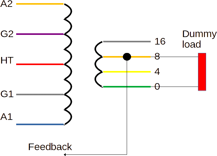
Wiring up a push pull output transformer – primary windings
How to design an isolated, high frequency, push-pull dc/dc converterSimulation diagram for push pull inverter with center tap transformer .
.


Push–pull with transformer. | Download Scientific Diagram

Push Pull Switching Transformer Design

Transformer Push–pull Output Push–pull Converter Alternating Current

Class b push pull amplifier experiment theory

Wiring up a Push Pull output transformer – Primary Windings

DC to DC Converter using Push Pull Topology with SG3525

Simulation Diagram For Push Pull Inverter With Center Tap Transformer