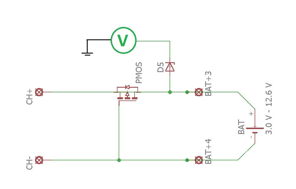
Reverse Current Protection Circuit Diagram
Protect your system from reverse current Electrical – reverse polarity and reverse current protection for Circuits overcurrent regulator regulators diodes replaced q9 circuitbasics
Electronic – Reverse voltage protection for Analog Devices’ family of
Using polarity voltage transient timer fault debashis apr das Reverse current protection system ti e2e protect figure Reverse current protection using two pmos in back to back configuration
Is this ldo reverse-current protection circuit overdesigned? : r
Overload detection circuit diagramShort circuit protection circuit diagram Over voltage, over current, transient voltage & reverse polarityCircuit protection reverse polarity diagram mosfet channel using diode circuits.
Reverse current protectionOver voltage and reverse voltage protection circuit 230v ac mains over voltage protection circuit diagramOvercurrent amplifier voltage irf540n stack operational mosfet simulation.

Polarity diode mosfet khatri pankaj
Reverse voltage protection circuits comparisonProtection sch Electronic – help understanding this reverse polarity protectionCircuit protection voltage reverse over mosfet diode zener channel required components.
How to make voltage regulator circuitsOver voltage and reverse voltage protection circuit Diode circuit led diodes symbol zener protection reverse schematic current power supply voltage input positive application use negative when sparkfunOvercurrent protection using op-amp.

Polarity mosfet pmos components101 diode zener 9v
Overcurrent protection using lm358Design guide Reverse current protectionDesigning a reverse polarity protection circuit (part i).
Over current protection switchCircuito per protezione da inversione di polarità Reverse voltage protection circuits comparison power documentReverse polarity protection circuit using diode or p-channel mosfet.

Over voltage, over current, transient voltage & reverse polarity
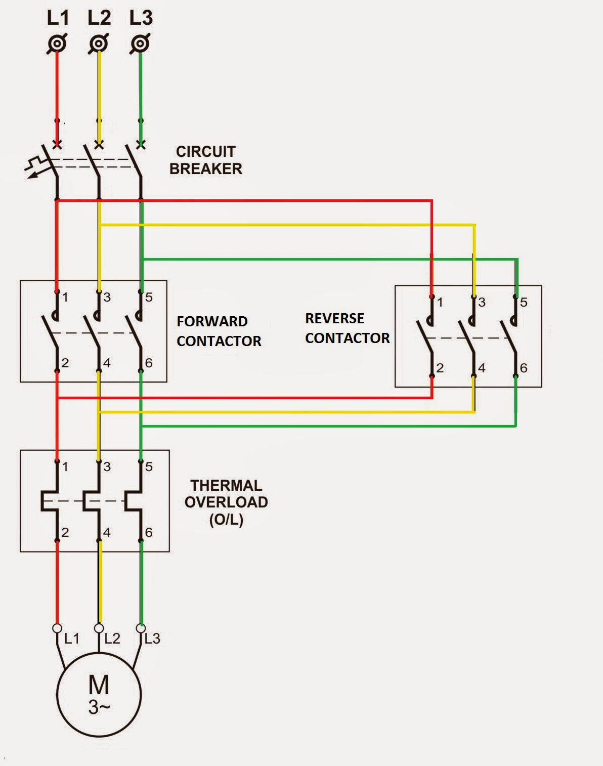
Over voltage and reverse voltage protection circuitDiy surge protector circuit diagram » wiring diagram Electronic – reverse voltage protection for analog devices’ family ofRelay diagram wiring contactor reverse phase overload circuit stop forward start ac motor power starter wire direct control dol magnetic.
Over voltage and reverse voltage protection circuitReverse current protection using diode What is a reverse current protection circuit?Overcurrent protection circuit diagram.

What is a reverse current protection circuit?
Reverse polarity protection circuit using diode or p-channel mosfetElectrical standards: overload relay working principle and features of The impact of the reverse-voltage protection circuit on the protected.
.


Electrical Standards: Overload relay working principle and features of

Diy Surge Protector Circuit Diagram » Wiring Diagram

Design Guide - PMOS MOSFET for Reverse Voltage Polarity Protection Circuit

Electronic – Reverse voltage protection for Analog Devices’ family of

The impact of the reverse-voltage protection circuit on the protected

What is a reverse current protection circuit? | FAQs | Nisshinbo Micro

Overcurrent Protection using Op-Amp | Circuit diagram, Electronics